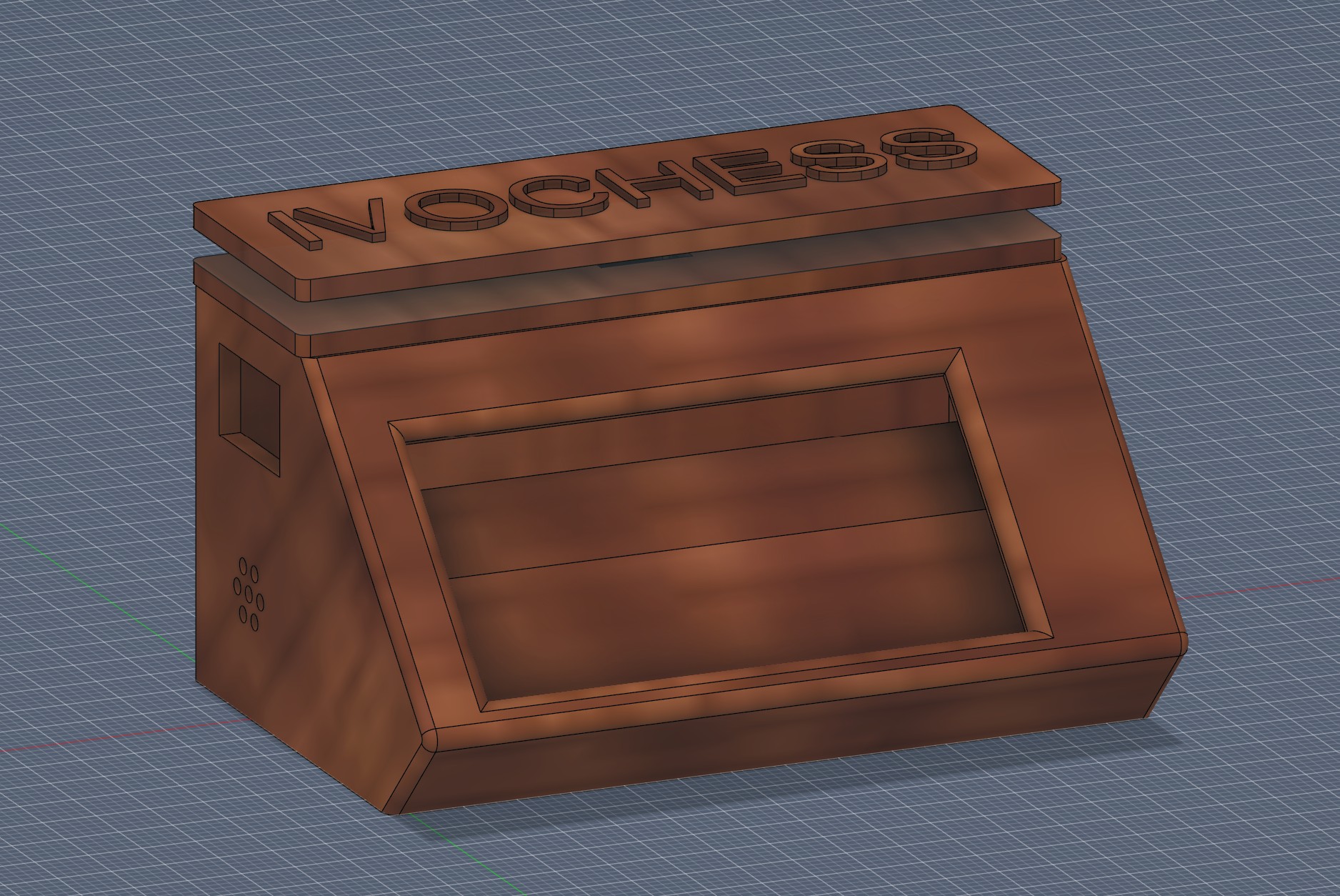
An assembled v2.0 prototype — physical button and speaker wired in alongside the original display, LED, and battery connections.
Six connections: the e-paper display, the LED strip, the battery, the on/off switch, the v2.0 physical button, and the v2.0 speaker. Every XIAO ESP32C6 pin used here is labeled directly in silkscreen on the board itself — match the label, not the position, and you can't go wrong.
An assembled v2.0 prototype — physical button and speaker wired in alongside the original display, LED, and battery connections.
The Waveshare 2.13" HAT connects over SPI, plus two control lines (DC, RST) and one status line (BUSY). It ships with a ribbon cable already attached to the panel and a set of loose jumper wires for the pin header — use those.
| Waveshare pin | XIAO ESP32C6 pin | Role |
|---|---|---|
| VCC | 3V3 | Power |
| GND | GND | Ground |
| DIN | D10 | SPI data (MOSI) |
| CLK | D8 | SPI clock (SCK) |
| CS | D9 | Chip select |
| DC | D4 | Data/command |
| RST | D3 | Reset |
| BUSY | D5 | Busy status (input) |
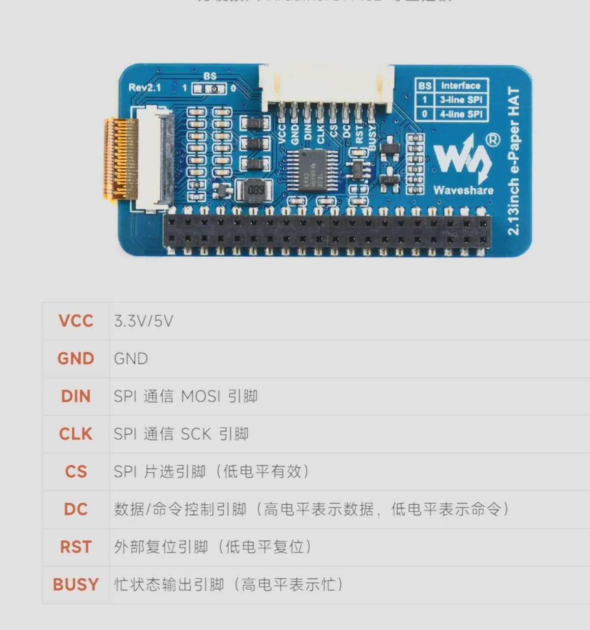
D3–D5, D8–D10) match the firmware's config.h exactly. If you ever want to move the display to different pins, update EPD_CS/EPD_DC/EPD_RST/EPD_BUSY there to match.An 8-pixel addressable strip, wired as a single data line — only the IN end connects to anything; the OUT end (for chaining more LEDs) is left unconnected.
| LED strip pin | XIAO ESP32C6 pin |
|---|---|
| VCC | 3V3 |
| GND | GND |
| IN | D7 |
| OUT | not connected |
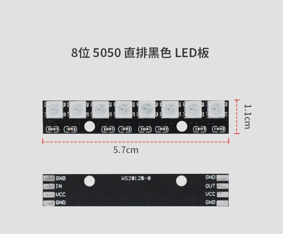
The number of LEDs actually driven is configurable in the webadmin software — it doesn't have to match all 8 physically wired pixels.
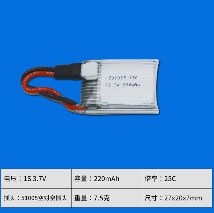
The XIAO ESP32C6 has onboard LiPo charging — solder the battery straight to its B+/B- pads on the underside of the board, with the switch in line on the positive lead only. A small two-resistor voltage divider off the same B+ line is what lets the firmware show a battery percentage at all.
| Connection | Goes to |
|---|---|
| Battery + (red wire) | Switch — terminal 1 |
| Switch — terminal 2 | XIAO B+ pad |
| Battery − (black wire) | XIAO B- pad, directly |
The XIAO ESP32C6 has no built-in battery-sense pin — the firmware reads charge level off D1 through a simple voltage divider you add yourself: two resistors from the battery's positive line down to ground, with the midpoint tapped into D1.
| Connection | Goes to |
|---|---|
| XIAO B+ pad | R1 — 100kΩ |
| R1 other end | Sense node |
| Sense node | R2 — 68kΩ → GND, and a wire to XIAO D1 |
D1 — comfortably under the ESP32's 3.3V ADC limit, so there's no risk of over-volting the pin even with normal resistor tolerance. The pair's raw ratio is 0.405; the firmware's VOLTAGE_DIVIDER_RATIO in config.h is set to 0.395 instead, calibrated against a real multimeter reading on the battery — if you build this yourself, do the same: compare the displayed percentage to an actual voltage reading and nudge that constant if it drifts.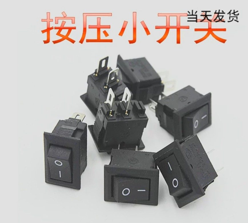
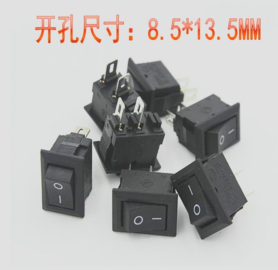
Panel-mount hole: 8.5 × 13.5mm. It's a simple 2-position on/off switch — if yours has a third pin (some rocker switches share a body with a lit variant), only two of the three are used; a quick continuity check with a multimeter shows which two switch together.
A new v2.0 addition: a 2-leg momentary switch (normally-open, springs back on release) mounted on top of the clock.
| Button leg | Goes to |
|---|---|
| Leg 1 | XIAO D0 |
| Leg 2 | XIAO GND |
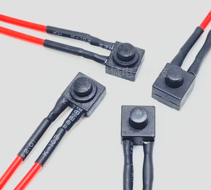
GND.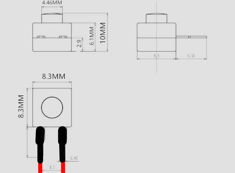
Another v2.0 addition: a 25mm passive speaker. Passive means it has no built-in amplifier — it can't be wired directly to a microcontroller pin. It needs a simple transistor driver circuit instead.
Extra parts needed: 1x generic NPN transistor (S8050, 2N2222, or any equivalent), 1x 1kΩ resistor (transistor base), 1x 10kΩ resistor (pulldown, optional but recommended).
XIAO D2 ----[1kΩ resistor]---- Transistor base (NPN)
                                Transistor emitter ---- GND
                                Transistor collector ---- Speaker "-" (black wire)

XIAO 3V3 ------------------------------------------------ Speaker "+" (red wire)

XIAO D2 ----[10kΩ resistor]---- GND   (pulldown - prevents an audible
                                        "click" at boot before the firmware
                                        configures the pin - optional,
                                        recommended)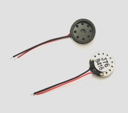
1kΩ base resistor limits current to a few mA — enough to saturate the transistor and drive the speaker safely. No flyback diode needed (that's only for inductive loads like relays or motors, not a small speaker at this power level). Sound is generated as a PWM square wave from the microcontroller pin; the transistor only amplifies the current.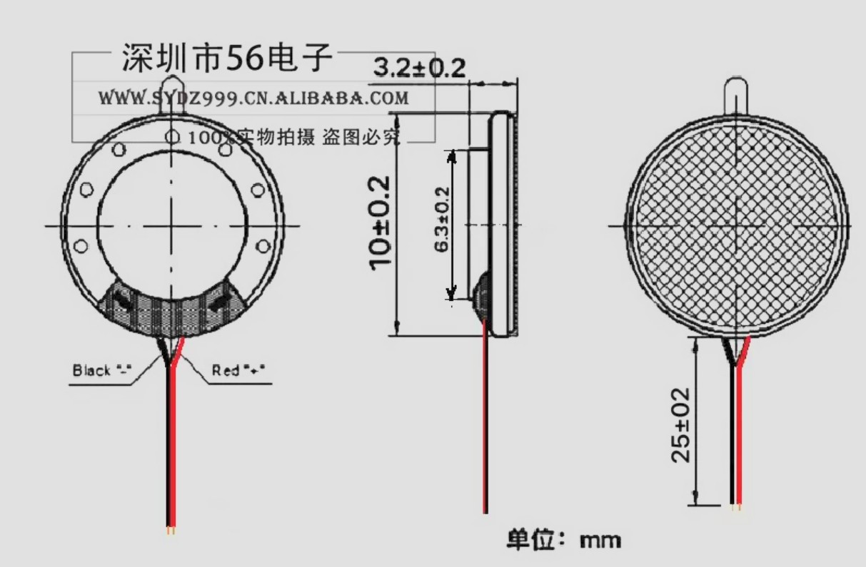
The two new v2.0 connections, at a glance. Neither pin conflicts with the existing v1 wiring (display SPI, LEDs, and battery sensing all use different pins).
| Component | XIAO pin | GPIO |
|---|---|---|
| Physical button | D0 | GPIO0 |
| Speaker driver (PWM) | D2 | GPIO2 |